|
Welcome! |
[Home] [PMWIN] [3D Visualization] [ASMWIN] [Downloads] [Links] |
|
|
|||
| by Wen-Hsing Chiang | Last Update: December 05, 2003 | ||
|
|
- Introducing Processing
Modflow for Windows - Access All Memory - Packages Supported - MT3D Supported - Support PEST for Automatic Calibration - Powerful Modeling Tools - Stochastic Modeling - Graphics Output - Extensive Online Help
Introducing
Processing Modflow for Windows
|
||||||||||
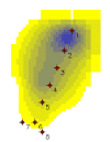 |
| Development of a contamination plume during remeadiation. The model is described in the user's manual of MT3D. |
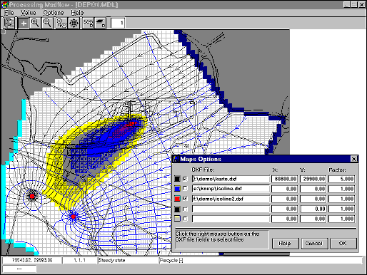
PMWIN is capable of using all available memory. PMWIN can handel models with up to 80 layers and 1000 stress periods, and each model layer can consist of up to 2000 × 2000 cells. The coordinate system can be defined by the user. The model grid can be shifted, rotated, refined and overlaid on up to five DXF-background maps. Model data can be specified for each finite-difference cell individually, in the form of zones, or even automatically interpolated by the Field Interpolator.
PMWIN
supports the simulation of the effects of wells, rivers,
drains, head-dependent boundaries, recharge and
evapotranspiration. Five additional packages of MODFLOW
are supported by PMWIN - HFB1, CHD1and IBS1- for
simulating slurry walls and calculating compaction. The
supported packages are listed below:
Basis Package(BAS1)
Block-Centered Flow Package 2 (BCF2)
Direct Solution Package (DE45)
Drain Package (DRN1)
Evapotranspiration Package (EVT1)
General-Head Boundary Package (GHB1)
Horizontal-Flow Barrier Package (HFB1)
Interbed-Storage Package (IBS1)
LKMT Package (this package creates interface files to
MT3D)
Output Control Options (OC)
Preconditioned Conjugate Gradient Package 2 (PCG2)
Reservoir Package (RES1)
River Package (RIV1)
Recharge Package (RCH1)
Strongly Implicit Procedure Package (SIP1)
Slice-Successive Overrelaxation Package (SOR1)
Streamflow-Routing Package (STR1)
Time-Variant Specified-Head Package (CHD1)
Well Package (WEL1)
PMWIN supports the use of MT3D (version 1.x and MT3D96) to simulate changes in concentration of single species miscible contaminants in groundwater considering advection, dispersion and chemical reactions. There are four soluition schemes for the advecton term - the method of characteristics (MOC), the modified method of characteristics (MOC), the hybrid method of characteristics (HMOC) and the pure finite-difference method. In MT3D, the concentration change due to dispersion alone is solved with a fully explicit central finite-difference scheme. Chemical reactions supported by the MT3D transport model include equilibrium-controlled sorption reactions and first-order irreversible rate reactions, such as redioactive decay or biodegradation.
The purpose of PEST (which is an acronym for Parameter ESTimation) is to assist in data interpretation and in model calibration. If there are field or laboratory measurements, PEST can adjust model parameters and/or excitation data in order that the discrepancies between the pertinent model-generated numbers and the corresponding measurements are reduced to a minimum. It does this by taking control of the model (MODFLOW) and running it as many times as is necessary in order to determine this optimal set of parameters and/or excitations. PMWIN helps the user to inform PEST of assigning the adjustable parameters and excitations. PMWIN provides comprehensive supports to PEST. All you have to do is to specify the observation data and define zones of parameters and send them to a Parameter List. It is all accomplished with a few clicks of the mouse.
A New Particle
Tracking Model PMPATH included
![]()
PMPATH is an
advective transport model running independently from
PMWIN. PMPATH retrieves the groundwater models created in
PMWIN and simulation result files from the flow model
MODFLOW. A semi-analytical particle tracking scheme is
used to calculate the groundwater paths and travel times.
Both forward and backward particle tracking are allowed
for steady-state and transient flow simulations. Through
the interactive graphical modeling environment of PMPATH,
you can place particles and perform particle tracking
with just a few mouse clicks. While most available
particle tracking models need postprocessors for
visualization of computed paths and times data, PMPATH
calculates and shows the pathlines and travel time marks
simultaneously. Moreover, PMPATH provides various
on-screen graphical options including head contours,
drawdown contours and velocity vectors for any selected
model layer and time step.
Field
Interpolator
![]()
Numerical ground water models require areally distributed
parameters (e.g., hydraulic conductivity or hydraulic
heads, etc.) be assigned to each cell in the model
domain. Usually, the modeler obtains a parameter
distribution in the form of XYZ scattered data points.
The field interpolator interpolates the XYZ data to each
model cell. The model grid can be irregularly spaced.
Four interpolation methods are currently provided,
including Kriging, Shepard's Inverse Distance and
triangulation methods developed by Akima and Renka.
Digitizer
![]()
Using the Digitizer you can digitize, shift or delect
points and assign a value to each of these points. You
can save or load the points of the current layer in or
from an XYZ file. An XYZ file can be accepted by the
Field Interpolator.
Graph
Viewer
![]()
You can display temporal development curves of the
measured values as well as simulation results including
hydraulic heads, drawdowns, concentration,
preconsolidation heads, compaction of a model layer and
subsidence of an entire aquifer. Using the simulation
results and user-specified observation values, PMWIN can
create scatter diagrams, which are often used to present
the calibration results. The observed values are plotted
on one axis and the calculated values on the other. For
exact agreement between measurement and simulation, all
points would lie on the 45° line. The narrower the area
of scatter around the line, the better is the match.
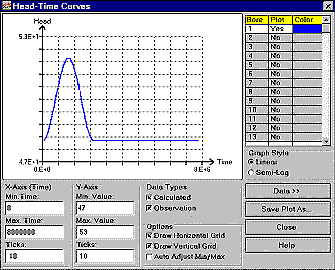
Head vs. time curve generated by the Graph Viewer
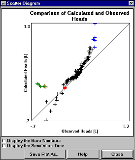
A scatter diagram generated by the Graph Viewer
View
your Results with the powerful Result Extractor
![]()
This powerful tool allows you to extract results from any
stress period, time step and layer and put them into a
spread sheet. You can examine the results, create contour
plots with PMWIN or save them in ASCII format or even
SURFER compatible files. The extractable result files
include hydraulic heads, drawdown, cell-by-cell flow
terms, preconsolidation head, compaction, subsidence and
concentration.
Calculation
of Subregional Water Budget
![]()
There are situations in which it is useful to calculate
flow terms for various subregions of the model. An
improved Water Budget Calculator allows you
to calculate budget for user-specified zones and the
exchange of flows between zones.
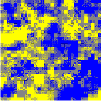
In
stochastic modeling, uncertainty due to unknown
small-scale distribution of the model parameters is
addresses directly by assuming that the parameters are
random variables. The Field Generator of PMWIN
generates synthetic fields with (lognormally)
heterogeneously-distributed transmissivity or hydraulic
conductivity and allows you to incorporate effects and
influences of unknown small-scale heterogeneities into
the groundwater model. This capablity allows you to do
stochastic modeling within PMWIN.
 |
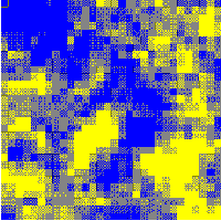 |
| Random fields generated and displayed by PMWIN. A mean value of -2.3 and standard deviation 0.5 (both log10 based) were used by the Field Generator. The ratio of correlation length to the field width is 0.1. | |
PMWIN provides the WYSIWYG (What You See Is What You Get) capability. It can create contour maps or solid fill plots of input data or simulation results. Solid Fill can utilize the full range of RGB values to fill cells with different colors. It is very useful for displaying concentration plumes or distributions of parameters. Contours can be added to solid fill plots. Velocity vectors and pathlines with time marks can be created by PMPATH for Windows. Report-quality graphics may be saved to a wide variety of file types, including SURFER, DXF, HPGL and BMP (Windows Bitmap). Through the use of DXF files, you can use CAD or graphics software (such as AutoCAD or CorelDraw) to overlay as many plots as you wish.
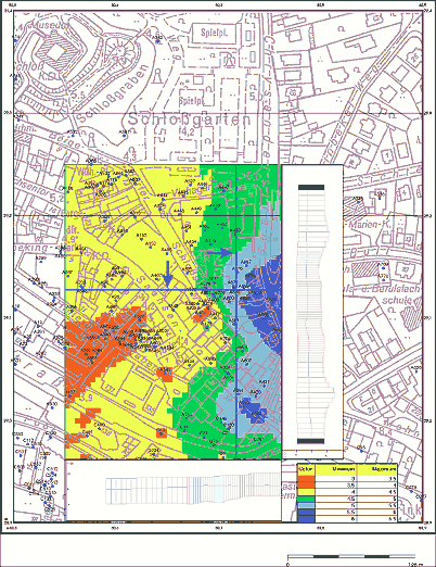 |
| Elevation distribution and Cross-sections overlaid on a background bitmap. |
PMWIN features an online help system and includes a comprehensive 200-page user's guide with a step-by-step tutorial, explanations of all applications and examples, and the underlying theory of all supported packages. The examples include a pumping test application, stochastic modeling, model calibration with PEST, simulation of solute transport and the other practical problems from the STR1, IBS1 and BCF2 packages.